Overview
The S□-M series uses mineral oil as the insulation system; its tank treatment meets the special outdoor demands of metallurgical and petrochemical plants and of humid, polluted regions.
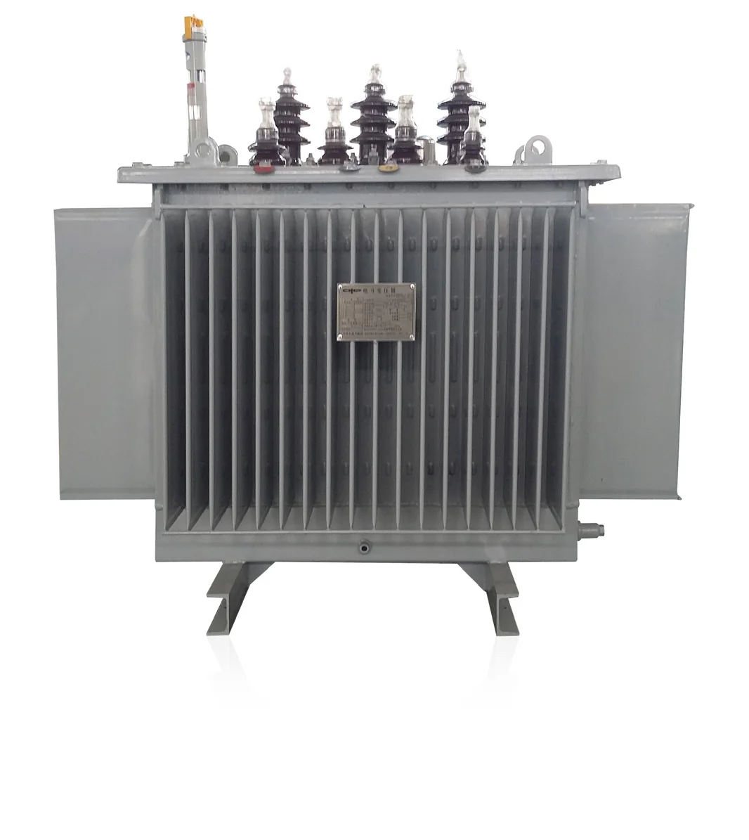
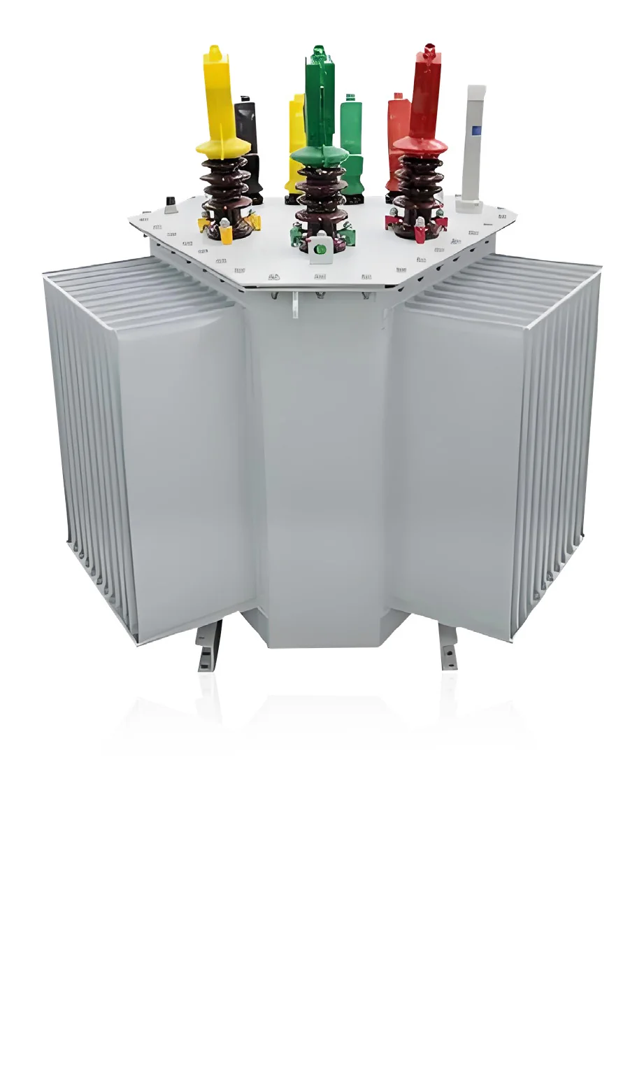
Sealed mineral-oil distribution transformers, 30–2500 kVA at 10/10.5 kV — grain-oriented core with multi-step 45° mitred joints, corrugated tank breathing with the oil, maintenance-free with no oil change.
The S□-M series uses mineral oil as the insulation system; its tank treatment meets the special outdoor demands of metallurgical and petrochemical plants and of humid, polluted regions.
Core of premium cold-rolled grain-oriented silicon steel, stacked with multi-step 45° fully mitred joints
Low no-load and load losses in service
Cylindrical winding structure with balanced ampere-turns — strong short-circuit withstand
Elastic corrugated tank or panel radiators absorb oil volume change from heating and cooling
Tank surface de-rusted, de-greased and phosphated before primer and topcoat — fit for metallurgy, petrochemical and humid-polluted outdoor sites
Maintenance-free: no insulating-oil replacement
Three-phase · loss-level code · sealed type · rated capacity (kVA) · system nominal voltage (kV)
Specifications are representative and may vary by configuration and region. Final figures are confirmed on the project datasheet.
Tell us about your load profile and site conditions — our engineers will help you size the right HiStore configuration.
Unable to display the PDF inline. Use the button below to open it in a new tab.
Open PDF in new tab