LV Switchgear

GCS Withdrawable LV Switchgear

Computer-interface-ready withdrawable switchboard for plants and petrochemical sites: 380/660 V up to 4000 A, busbars withstand 80 kA/176 kA, MCC cabinets pack up to 22 circuits with 32-pair secondary connectors.

Factory-direct supply Worldwide delivery & export documentation 12-month warranty · extended options
  • Higher thermal capacity of adapters markedly cuts extra temperature rise on connectors, cable heads and partit
  • Clear, reliable segregation between units and compartments confines any fault to the smallest scope
  • Flat-laid busbars give excellent dynamic-thermal stability, withstanding 80 / 176 kA short-circuit impact
  • Up to 22 circuits in one MCC cabinet — sized for big-unit power plants and petrochemical motor groups
  • External cables land in a dedicated cable compartment with top/bottom entry; CTs mounted inside for easy servi
  • Current-limiting reactors can cap fault current and stabilise bus voltage, easing component duty
At a glance

Built to perform, year after year

AC 380(400) / 660 V
Main-circuit rated voltage
AC 220·380(400) / DC 110·220 V
Auxiliary-circuit voltage
50(60) Hz / 660(1000) V
Rated frequency / insulation voltage
≤4000 / 1000 A
Rated current horiz. / vert. (MCC)
A closer look

Engineered around safety, efficiency and uptime

Overview

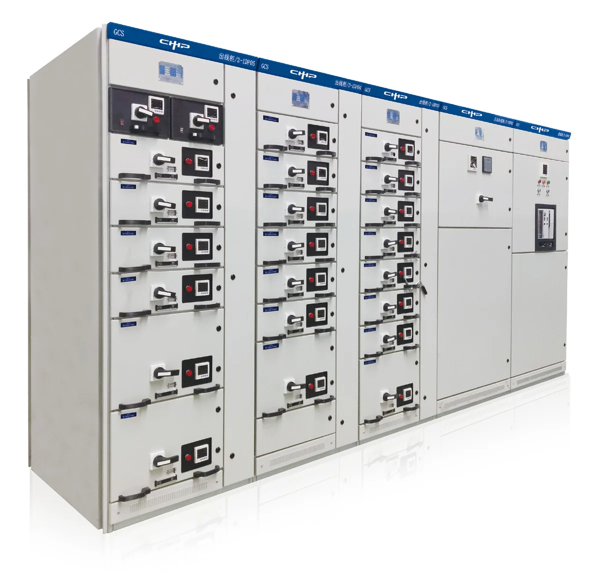
GCS withdrawable LV switchgear serves distribution systems across power, petroleum, chemical, metallurgical, textile and high-rise sectors — three-phase 50(60) Hz, 380(400)/(660) V, up to 4000 A — for distribution, centralised motor control and reactive compensation, especially where computer interfacing is required.

Design features

Higher thermal capacity of adapters markedly cuts extra temperature rise on connectors, cable heads and partitions
Clear, reliable segregation between units and compartments confines any fault to the smallest scope
Flat-laid busbars give excellent dynamic-thermal stability, withstanding 80 / 176 kA short-circuit impact
Up to 22 circuits in one MCC cabinet — sized for big-unit power plants and petrochemical motor groups
External cables land in a dedicated cable compartment with top/bottom entry; CTs mounted inside for easy service
Current-limiting reactors can cap fault current and stabilise bus voltage, easing component duty
Drawer units carry abundant secondary connectors (32 pairs for ≥1 unit, 20 pairs for 1/2 unit) for computer and automation interfaces

Auxiliary circuits

Auxiliary diagrams follow the Technical Code for Auxiliary Power Design in Thermal Power Plants, fitting station-service LV systems of plants and substations as well as industrial and high-rise distribution. Schemes are organised by functional units — incoming, feeder (PC) and motor feeder (MCC) operation control — matched to the main-circuit schemes.

Technical specifications

Full specifications

Technical parameters
Main-circuit rated voltage
AC 380(400) / 660 V
Auxiliary-circuit voltage
AC 220·380(400) / DC 110·220 V
Rated frequency / insulation voltage
50(60) Hz / 660(1000) V
Rated current horiz. / vert. (MCC)
≤4000 / 1000 A
Busbar short-time withstand (1 s)
50 · 80 kA
Busbar peak withstand (0.1 s)
105 · 176 kA
PF test voltage main / aux (1 min)
2500 / 1760 V
Busbar system / protection
三相四线·五线 A.B.C.PE.N / IP30·IP40

Specifications are representative and may vary by configuration and region. Final figures are confirmed on the project datasheet.

Ready to power your next project?

Tell us about your load profile and site conditions — our engineers will help you size the right HiStore configuration.